DRIVE AXLE - FULL FLOATING
1988 Jeep Cherokee
Drive Axles - Dana Full-Floating Axles Jeep Front & Rear Drive Axles
DESCRIPTION
The axle assembly is an integral carrier type with hypoid gear ring and pinion. Stamped steel cover is removable for inspection and repair of differential. Vehicle loads are carried by axle housings. Axle shafts of "full-floating" rear assemblies may be removed without disturbing wheel bearings.
Drive pinion depth, pinion bearing preload and differential side bearing preload are all set by shims.
See LOCKING HUB and 4WD STEERING KNUCKLE articles in this section for removal and installation procedures for these front drive axle component parts.
AXLE RATIO & IDENTIFICATION
A metal tag on axle is stamped with gear ratio, part numbers and limited slip identification. To determine drive axle ratio, refer to MODEL IDENTIFICATION BY RING GEAR SIZE table.
MODEL IDENTIFICATION BY RING GEAR SIZE
Model Ring Gear Diameter
44 8.50"
9.75"
9.75"
70 10.50"
80 11.25"
FRONT HUB, BEARING, SPINDLE & AXLE SHAFT R & I
FRONT HUB BEARING ADJUSTING SPECIFICATIONS
Application (1) Ft. Lbs. (N.m)
Adjusting Nut
Step 1 50 (68)
Step 2 Back Off 20 °
Lock Nut 50 (68)
(1) - While Rotating Hub.
REMOVAL (CHEROKEE, COMANCHE & WAGONEER)
Raise and support vehicle. Remove tire and wheel assembly.
Remove disc brake caliper and support out of way.
Match mark disc rotor and hub and remove disc rotor.
Remove cotter pin, nut lock and axle hub nut. Remove hub-to-knuckle
bolts. Pull hub assembly off axle shaft. Pull axle shaft through
knuckle to remove. Inspect axle shaft "U" joint and shaft splines for
wear. Replace as necessary.
Press hub out of bearings. Remove seals and bearings.
Inspect bearings and races for wear and pitting. Replace bearing and race together.
INSTALLATION
Install axle shaft through knuckle and engage in axle gear
splines. Pack bearings with multi-purpose grease and fill cavities in
bearing hub. Install new seals.
Press hub into bearings. Install hub assembly on axle
shaft and install bolts. To complete installation, reverse removal
procedure. See TORQUE SPECIFICATIONS table at end of this article.
INTERMEDIATE AXLE SHAFT R & I
REMOVAL (DISCONNECT AXLE MODELS)
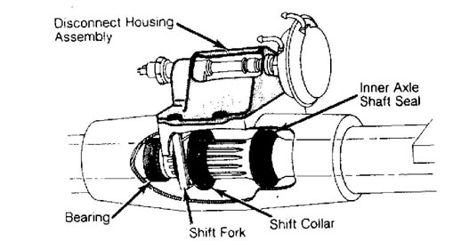
Fig. 1: View Of Axle Disconnect Assembly Courtesy of Chrysler Motors.
INSTALLATION
Remove outer axle. See FRONT HUB, BEARING, SPINDLE & AXLE
SHAFT in this article.
Remove axle assembly inspection cover and drain fluid.
Remove vacuum and electrical connections at disconnect housing
assembly. Remove bolts and pull disconnect housing from axle tube. See
Fig. 1.
Remove intermediate shaft retaining clip on inner end of
axle shaft. Carefully slide intermediate axle shaft through seal and
out end of axle tube. Remove shift collar.
Inspect intermediate shaft bearings and seals for wear. If
replacement of bearings or seal is necessary, use recommended tools.
On Jeep, use Tool Set (J-34659), Slide Adapter (J-34659-4)
and Over Rod (J-34659-3) to replace intermediate shaft bearings and
seal.
Coat intermediate shaft with lubricant and carefully slide
through seal and engage in drive axle splines. Install retaining clip.
Install shift collar on axle shaft. Install outer axle
shaft and check for smooth operation of shift collar.
Apply bead of silicone sealer to inspection cover and
install cover. Fill axle housing with 2.5 pts. (1.2L) of 75W 90 gear
oil. Pour a small amount of gear oil on shift collar and install
disconnect housing. Ensure shifting fork is properly positioned in
shift collar.
To complete installation, reverse removal procedure.
Tighten all bolts and nuts to specification. See TORQUE SPECIFICATIONS table at end of this article.
FRONT AXLE ASSEMBLY R & I
REMOVAL (CHEROKEE, COMANCHE, WAGONEER)
Raise and support vehicle. Remove tire and wheel assembly.
Remove hubs, spindles and axles. See FRONT HUB, BEARING, SPINDLE &
AXLE SHAFT in this article.
Disconnect vacuum hoses and electrical connections from
shift motor. Disconnect stabilizer bar, track bar and steering damper.
Disconnect drive shaft at pinion yoke and tie to frame.
Remove left and right tie rod ends from knuckles.
Support axle assembly on floor jack. Remove lower shock
mounts. Disconnect axle housing-to-frame control arms at axle. Lower
floor jack slowly and remove axle assembly. Remove coil spring lower
bracket and coil spring.
INSTALLATION
1) Place axle housing on floor jack and position under
vehicle. Install coil springs and raise assembly into position. Ensure top of coil springs seat in spring pocket.
2) Check all bushings and mounting hardware for wear or
damage. To complete installation, reverse removal procedure. Tighten
all bolts and nuts to specification. See TORQUE SPECIFICATIONS table
at end of this article. Fill axle assembly with gear oil. Check wheel
alignment.
REAR HUB, BEARINGS & AXLE SHAFTS R & I
Raise and support vehicle. Remove tire and wheel assembly.
Remove axle flange nuts or bolts. If nuts are used, rap center of axle
flange sharply with hammer to loosen tapered dowels. Remove bolts or
dowels and pull axle shaft out of hub.
Depending on application, bend back ears of lock washer,
or remove locking wedge from nut, or remove snap ring and key. Remove
bearing adjusting nut(s) and remove hub assembly.
Remove inner hub seal and bearing. Inspect bearings and
races for wear. To replace bearing, drive outer race from bearing hub
using a punch and hammer. Install new race being careful not to chip
or dent race. Ensure new race is seated in hub.
Pack bearings with multi-purpose grease. Install new seal.
Carefully install hub on axle spindle to avoid damaging seal lip and
spindle threads.
Install outer bearing and adjusting nut. Tighten bearing
adjusting nut in steps. See REAR HUB BEARING ADJUSTING SPECIFICATIONS
table. Install lock ring if used. Install spindle lock nut if used and
tighten to proper specification. See REAR HUB BEARING ADJUSTING
SPECIFICATIONS table.
REAR HUB BEARING ADJUSTING SPECIFICATIONS
Application
(1) Ft. Lbs. (N.m)
Adjusting Nut
Step 1 50 (68)
Step 2 Back Off 45 °
Lock Nut 50 (68)
(1) - While rotating hub.
6) Install new axle flange gasket or apply silicone sealer. Install axle and tighten bolts or nuts to proper specification. See TORQUE SPECIFICATIONS table at end of this article.
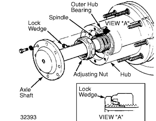
Fig. 2: Rear Hub & Bearing Adjuster
REAR AXLE ASSEMBLY R & I
REMOVAL
Raise and support vehicle. Remove wheels, hubs and axles.
See REAR HUB, BEARINGS AND AXLE SHAFTS.
Remove lower shock mounts and stabilizer bar mount.
Disconnect drive shaft and tie up. Remove hydraulic brake line at
junction and plug.
Disconnect park brake cables and hydraulic brake lines to
wheel cylinders or calipers. Remove brake backing plate or caliper.
Support axle housing with floor jack and remove leaf
spring "U" bolts. Carefully lower axle housing and remove from
vehicle.
INSTALLATION
Place axle housing on floor jack. Raise axle and install "U" bolts and nuts. To complete installation, reverse removal procedure. Tighten all bolts and nuts to specification. See TORQUE SPECIFICATIONS table at the end of this article and REAR HUB BEARING ADJUSTING SPECIFICATIONS table.
PINION SEAL & YOKE R & I
REMOVAL
Fig. 3: Removing Pinion Nut & Washer
Raise and support vehicle. Mark drive shaft-to-yoke
contact area for reassembly reference. Remove drive shaft-to-yoke
attaching nuts/strap bolts. Discard used strap bolts. Remove drive
shaft.
Using a breaker bar and Pinion Nut Remover (8614-01),
remove pinion nut and washer. See Fig. 3. Using Yoke Pullers (8614-
01), (8614-02) and (8614-03), remove yoke. See Fig. 4. Using Pinion
Seal Remover (J-9233 or J-7583) , remove pinion seal from front
differential housing. See Fig. 5.
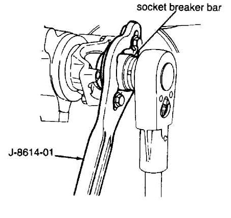
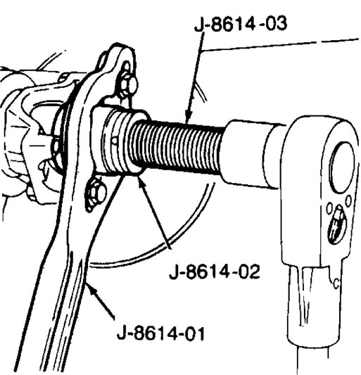
Fig. 4: Removing Front Drive Axle Yoke
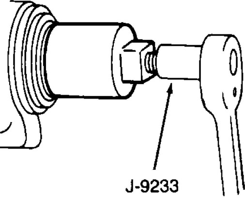
Fig. 5: Removing Pinion Seal
INSTALLATION
Using Seal Installer (J22661), drive new seal into front differential housing. See Fig. 6. Tighten yoke attaching nut to 210 ft. lbs. (285 N.m). Using NEW strap bolts, align and install drive shaft. Tighten strap bolts to 14 ft. lbs. (19 N.m). Fill differential with SAE 75W-90 gear lubricant.
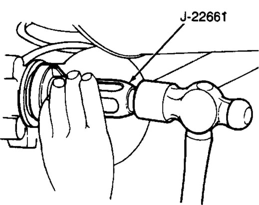
Fig. 6: Installing New Front Axle Shaft Seal
AXLE SHAFT OVERHAUL
NOTE: All front axle shafts except (Select-Trac) use Cardan "U"
joints and should be overhauled in same manner as drive shaft "U" joints.
DISASSEMBLY (SELECT-TRAC)
Cut and remove both outer boot clamps. Slide boot off
outer CV joint.
Using a block of wood seated on inner race, tap joint from
shaft. If shaft is clamped in a vise, be sure to use protective vise
jaws.
Tap outer CV cage with a brass punch until cage is tilted
out far enough to remove first ball bearing. Remove remaining ball bearings in same manner.
Rotate outer CV joint cage outward until it is at a 90
degree angle to installed position. Align 2 oblong holes in outer
joint cage with slots in interior wall of spindle housing and remove
cage and inner race.
Remove inner race from cage by aligning shoulder between
race grooves with inside of oblong cage holes. Rotate inner race out
of cage using larger of 2 openings in cage. Remove retaining ring,
spacer ring and outer boot.
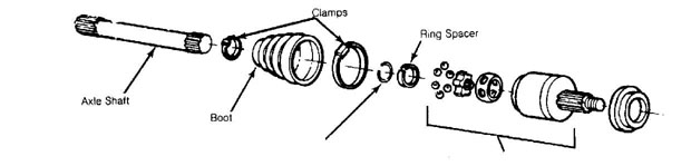
Retaining Ring
Constant Velocity {CV) Joint
Fig. 7: Exploded View of Jeep (Select-Trac) Drive Axle Courtesy of Chrysler Motors.
CLEANING & INSPECTION
Wash all parts in solvent and dry. Inspect inner and outer
ball races for damage. Inspect splined stub shaft for wear, cracks and
twisted splines.
Inspect all 6 balls for pitting, cracking or scoring.
Dulling of surface is normal. If any damage is found, replace entire
CV joint assembly. Polished areas in races and on cage spheres are
normal and DO NOT require joint replacement.
REASSEMBLY
Apply a light coat of CV grease on ball grooves of inner
and outer races. Install inner race into cage using a rotating action
opposite of removal. Inner race snap ring should face axle side.
Be sure ball bearing retaining ring is installed on inner
race side facing small end of cage. Align windows of cage with outer
race lands, and pivot cage with inner race into tilted position
(opposite of removal).
Install ball bearings one at a time into outer CV joint as
cage is tilted and rotated. After balls are installed into cage, pivot
cage and inner race into installed position.
Slide new seal clamp for small end of boot seal, boot seal
and seal retainer onto axle shaft. Coat inside lip (large diameter end
of seal) with CV grease. Slide seal retainer on end of seal.
Spread ears of bearing race snap ring, and slide CV joint
onto axle shaft until snap ring seats in groove. Pack joint with
approximately 1/2 of grease provided in seal kit. Apply remaining
grease inside seal.
Slide seal toward joint until small end of seal is in
groove in axle shaft. Position small clamp over small end of seal and
into groove and tighten.
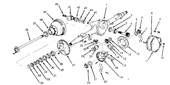
Carrier Housing
Shim Pack
Inner Pinion Bearing
Orive Pinion
Shim Pack
Side Bearing
Bearing Cap
8 Cover Gasket
9. Clip
Plug
Cover
Ring Gear
Thrust Washer
Side Gear
Thrust Washer
16 Pinion Gear
Lock Pin
Pinion Shaft
Differential Case
Bearing Cap
21 Shim Pack
Side Bearing
Side Gear
Thrust Washer
Pinion Gear
Thrust Washer
27 Backing Plate
Seal
Inner Hub Bearing
Snap Ring
Outer Hub Bearing
Adjusting Washer
Adjusting Nut
Lock Washer
Lock Nut
Axle Shaft
Axle Flange Gasket
Hub
Brake Drum
40 Flange Nut
41. Pinion Flange
42 Pinion Seat
Slinger
Outer Pinion Bearing
Shim Pack
Fig. 8: Exploded View Of Dana Full-Floating Axle Assembly
AXLE ASSEMBLY OVERHAUL
DISASSEMBLY
Drain lubricant. Remove axle shafts and housing cover. If
no side play is found in the differential case assembly, mount dial
indicator on pilot stud with tip against back of ring gear. Measure
runout of ring gear, marking ring gear and case at point of maximum
runout.
If runout total exceeds .006" (.15 mm), ring gear could be
loose or case could be damaged. Using .003" (.08 mm) feeler gauge, try
to force feeler gauge between cap and race. If it does, bearing race
may have been turning in carrier.
If race has been turning, carrier could be damaged.
Observe identifying letters stamped into bearing caps and face of
carrier sealing surface. Use these matched letters for reassembly
reference.
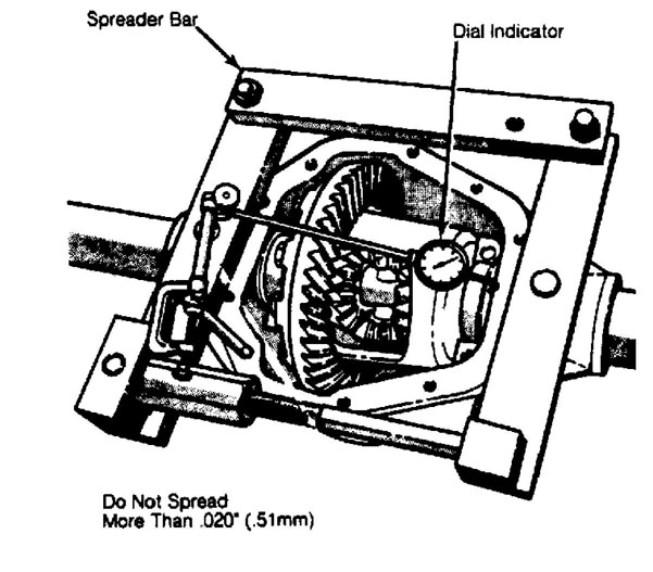
Remove side bearing caps. Use Housing Spreader (W-129-A on
Model 44; D-167 on Models 60, 61, 70 and housing to .015" (.38 mm). See Fig. 9.
to spread differential
CAUTION: DO NOT spread housing more than .020" (.51 mm). Permanent damage to housing could result.
29259
Fig. 9: Correct Procedure for Spreading Housing
Pry differential case out of housing. Remove spreader to
prevent carrier taking set. On models with side bearing shims between
carrier and side bearing outer race, record sizes and positions of
shims. Be careful not to damage machined surfaces of housing.
Put case in soft-jawed vise and remove ring gear bolts and
discard. Tap ring gear loose with soft mallet. If ring gear runout measured earlier exceeded .006" (.15 mm), repeat runout measurement of case without ring gear. Total runout of case should not exceed .003" (.08 mm).
Using Flange Holder Wrench (C-3281), remove drive pinion
nut and washer. Using holder wrench and Flange Puller (C-452), remove
drive pinion flange. Using Pinion Seal Puller (C0748), remove pinion
oil seal. Remove slinger, gasket, outer pinion bearing and preload
shim pack.
Remove drive pinion with inner bearing. Remove inner and
outer pinion bearing races. Remove and note thickness of shim pack
behind inner bearing race. Remove inner pinion bearing from pinion
shaft using Puller Press (DD-914-P) with Adapter Ring (DD-914-9) and
Pinion Bearing Puller Plates (C-293-39 on Model 44; DD-914-37 on Model
60 and 61; DD-914-95 on Models 70 and 80) .
NOTE: Pinion bearing adjusting shims may remain on pinion shaft, stick to bearing or fall loose. Collect and save them for reassembly.
9) Remove side bearings with Bearing Puller (C-293-PA),
Extension Plug (C-293-3 on Model 44; DD-914-7 on Models 60, 61, 70 and 80) and Puller Plates (C-293-18 on Model 44; DD-914-62 on Models 60, 61, 70 and 80). Record shim thickness and location for reassembly reference.
If differential case is a one-piece unit, drive out lock
pin holding differential pinion shaft to case. Remove differential
pinion shaft, gears and thrust washers (one for each gear).
If differential case is a 2-piece unit, mark both
differential case halves to aid reassembly in correct position. Remove bolts holding case halves together. Tap on top half of case to break it loose from lower half. Remove top half of case. Remove pinion gear spider, pinion gears, side gears and all thrust washers.
INSPECTION
Use cleaning solvent to rinse gears and bearings. Check
large end of bearing rollers where wear, if any, is evident. Check
pinion and flange splines for excessive wear. Ensure ring gear teeth
are in good condition.
Check differential case for cracks, scoring of side gears,
thrust washers and pinion thrust faces. Check fit of side gears to
case and to axle shaft splines. Look at pinion shaft and spacer for
scoring or excessive wear.
REASSEMBLY & ADJUSTMENTS
When reassembling and adjusting ring and pinion assembly,
pinion depth, pinion bearing preload, side bearing preload and
backlash between ring and pinion must be adjusted.
If only pinion shaft and ring gear are to be replaced and
carrier housing can be reused, compare pinion depth adjustment numbers
etched in faces of old and new pinion heads. See Fig. 10. Using
PINION DEPTH SHIM ADJUSTMENT SPECS table, correct shims can be
selected for new pinion shaft depth adjustment.
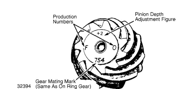
Fig. 10: Location of Pinion Gear Markings W/ Depth Adjustment Figures
NOTE: In order to use PINION DEPTH SHIM ADJUSTMENT SPECS table, old pinion shaft shim pack dimensions MUST be determined accurately. If original pinion shaft shim pack dimension cannot be determined accurately, Pinion Depth Gauge Set (D-271) must be used to properly determine pinion depth setting. Depth gauge set must also be used if new carrier housing is to be used.
PINION DEPTH SHIM ADJUSTMENT SPECS
PINION DEPTH SHIM ADJUSTMENT CHART (INCHES)
Old Pinion Marking | New Pinion Marking | ||||||||
-4 | -3 | -2 | -1 | 0 | + 1 | +2 | + 3 | + 4 | |
+ 4 | +0.008 | +0.007 | +0.006 | +0.005 | +0.004 | +0.003 | +0.002 | +0.001 | 0 |
+ 3 | +0.007 | +0.006 | +0.005 | +0.004 | +0.003 | +0.002 | +0.001 | 0 | -0.001 |
+2 | +0.006 | +0.005 | +0.004 | +0.003 | +0.002 | +0.001 | 0 | -0.001 | -0.002 |
+ 1 | +0.005 | +0.004 | +0.003 | +0.002 | +0.001 | 0 | -0.001 | -0.002 | -0.003 |
0 | +0.004 | +0.003 | +0.002 | +0.001 | 0 | -0.001 | -0.002 | -0.003 | -0.004 |
-1 | +0.003 | +0.002 | +0.001 | 0 | -0.001 | -0.002 | -0.003 | -0.004 | -0.005 |
-2 | +0.002 | +0.001 | 0 | -0.001 | -0.002 | -0.003 | -0.004 | -0.005 | -0.006 |
-3 | +0.001 | 0 | -0.001 | -0.002 | -0.003 | -0.004 | -0.005 | -0.006 | -0.007 |
-4 | 0 | -0.001 | -0.002 | -0.003 | -0.004 | -0.005 | -0.006 | -0.007 | -0.008 |
PINION DEPTH SHIM ADJUSTMENT CHART (MILLIMETERS)
Old Pinion Marking | New Pinion Marking | ||||||||
-10 | -8 | -5 | -3 | 0 | + 3 | + 5 | + 8 | + 10 | |
+ 10 | + 0.20 | + 0.18 | + 0.15 | + 0.13 | + 0.10 | + 0.08 | + 0.05 | + 0.03 | 0 |
+ 8 | + 0.18 | + 0.15 | + 0.13 | + 0.10 | + 0.08 | + 0.05 | + 0.03 | 0 | -0.03 |
+ 5 | + 0.15 | + 0.13 | + 0.10 | + 0.08 | + 0.05 | + 0.03 | 0 | -0.03 | -0.05 |
+ 3 | + 0.13 | + 0.10 | + 0.08 | + 0.05 | + 0.03 | 0 | -0.03 | -0.05 | -0.08 |
0 | + 0.10 | + 0.08 | + 0.05 | + 0.03 | 0 | -0.03 | -0.05 | -0.08 | -0.10 |
-3 | + 0.08 | + 0.05 | + 0.03 | 0 | -0.03 | -0.05 | -0.08 | -0.10 | -0.13 |
-5 | + 0.05 | + 0.03 | 0 | -0.03 | -0.05 | -0.08 | -0.10 | -0.13 | -0.15 |
-8 | + 0.03 | 0 | -0.03 | -0.05 | -0.08 | -0.10 | -0.13 | -0.15 | -0.18 |
-10 | 0 | -0.03 | -0.05 | -0.08 | -0.10 | -0.13 | -0.15 | -0.18 | -0.20 |
3) The pinion depth adjustment number is determined by manufacturer at time of assembly. Number represents distance best running position of pinion shaft deviates from "nominal" or standard distance between pinion gear face and center line of axle. See Fig. 11.
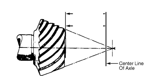
Axle Pinion Model Setting
60 — 3.125"-» (79.4mm)
70 — 3.500"-» (88.9mm)
32395
Fig. 11: Pinion Setting Standard Dimension
NOTE: Dimensions for Models 44, 61 and 80 not available.
NOTE: These are "nominal" distances from center of ring gear to
face of pinion shaft. Deviations are noted on pinion face.
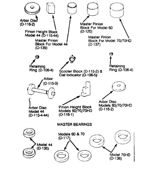
4) Pinion Depth Gauge Set (D-271) allows shim pack adjustments to be made without having to remove and replace differential bearings. See Fig. 12.
28624
Fig. 12: Pinion Depth Gauge Set (D-271)
NOTE: This set can be used on Models 44, 60, 61, 70 and 80. 5) Place differential case in holding fixture or vise.
Lubricate all parts with gear oil. On one-piece case, place side gears and new thrust washers in case. Place differential pinions and new thrust washers in case. Rotate side gears until holes in pinion gears and washers line up with holes in case. Install differential pinion shaft. Install lock pin after aligning hole in shaft with hole in case. Peen edge of hole to keep pin in place.
On 2-piece case, Install side gears and new washers with
pinion gears and cross shaft into half of case that is flanged. Put
top half of case on bottom half. Align scribe marks made before
disassembly. Tighten all bolts finger tight. Tighten bolts alternately
to 65-70 ft. lbs. (88-95 N.m).
On all one and 2-piece case units, inspect ring gear and
case for any burrs or nicks. Install ring gear and tighten NEW ring
gear bolts evenly in alternating pattern to specification.
Install Master Bearings into case. Use (D-135) for Model
44 or (D-117) for Models 60, 61, 70 and 80. Install differential case
in carrier. Install and tighten side bearing caps finger tight over
master bearings. Caps must be in same location as marked during
disassembly. Mount dial indicator on carrier with indicator tip
against back of ring gear.
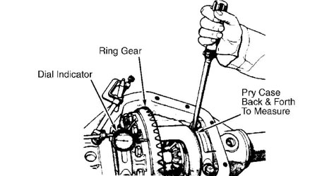
Pry case assembly to one side of carrier. Zero dial
indicator and pry case in opposite direction. See Fig. 13. Record
reading. This indicates thickness of shim pack necessary to eliminate
clearance between case and side bearing races.
10) Actual placement of shim pack and necessary preload will
be calculated after drive pinion is installed and pinion depth has
been determined. Remove dial indicator. Remove bearing caps and
differential case from carrier.
NOTE:
If new differential side and pinion gears are used with new washers, gear backlash should be correct due to close machine tolerances. If old gears and/or washers are used, gear backlash must be checked.
32396
Fig. 13: Measuring Differential Case End Play
NOTE: If original ring and pinion is to be used, measure old shim packs and make up packs of same dimensions with new shims. Baffles are considered part of shim pack.
PINION DEPTH
Depth Gauge Set (D-271) is used to determine pinion depth.
Place Master Pinion Block (D-139 on Model 44; D-120 on Model 60 and
61; D-137 on Model 70; T80T-4020-F42 on Model 80) in pinion bore of
carrier. Put Arbor Discs (D-115-4-44 on Model 44; D-116-2 on Models
60,61 and 70; (T88T-4020-A) on Arbor (D-115-3). Install arbor in
carrier with discs riding in bearing bore.
Put Pinion Height Block (D-115-1-44 on Model 44; D-116-1
on Models 60, 61, 70 and 80) on top of master pinion block with side
against arbor. Place Scooter Block (115-2) with Dial Indicator (D-106-
5) on small step of pinion height block. Zero dial indicator with
scooter block flat on pinion height block.
Move scooter block so dial indicator tip touches arbor.
Move block back and forth (perpendicular to arbor) to get highest
reading. This reading, plus or minus value etched on pinion head, is
thickness of shim pack necessary for pinion bearing.
On Model 80, Use Gauge Tube (D81T-4020-F51) and Gauge
Block (D81T-4020-F56) to determine required thickness of shim pack.
On all models, measure shims separately with micrometer.
If baffle is used, its thickness must be included in shim pack. This
is also true if slinger is used between inner bearing and head of
pinion shaft. Place pinion height shim pack in carrier bore for inner
bearing race. Drive bearing race into carrier, making sure cup is
fully seated.
PINION BEARING PRELOAD
1) Drive outer pinion bearing into carrier housing. Press
inner pinion bearing onto pinion shaft using Press Tube (C-3095-A).
Ensure bearing seats fully. Insert pinion shaft into carrier. Install
outer bearing, slinger (if equipped), flange, washer and nut.
NOTE: Pinion preload shims and oil seal should NOT be installed at this time.
Using an INCH lb. torque wrench, tighten pinion nut until
10 INCH lbs. (1.13 N.m) rotational torque is required to move pinion
shaft. Recheck pinion depth with arbor and discs at this time. Place
pinion height block on face of pinion shaft.
Place dial indicator on small step of height block for
Model 44, 60 and 61 axles. Place dial indicator on high step of block
for Models 70 and 80 axles. Zero dial indicator and move it across
arbor to get highest reading. If reading is within .002" (.05 mm) of
etching on pinion face, pinion depth is correct.
NOTE: If pinion depth is not with .002" (.05 mm) of etched number on face of pinion, shim pack under inner bearing race must be changed before proceeding with differential settings.
4) Remove pinion nut, washer, flange, slinger and outer
bearing. Place preload shims (removed during disassembly) on pinion.
Install bearing and slinger. After lightly coating lips with gear oil,
install pinion seal in carrier housing. Install flange, washer and NEW
pinion nut. Tighten nut to specification. See TORQUE SPECIFICATIONS
table at end of this article.
5) Using an INCH lb. torque wrench, measure preload
(rotational torque) of pinion shaft. Rotational torque required to
keep pinion shaft turning freely and smoothly should be 20-40 INCH lbs. (2.3-4.5 N.m). If preload needs to be increased, remove a few shims and recheck. To decrease preload, add a few shims and recheck. See Fig. 14.
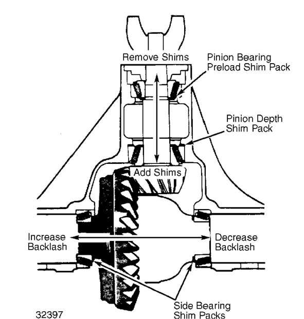
Fig. 14: Carrier Housing Shim Positioning
DIFFERENTIAL BEARING PRELOAD
1) Install differential case in housing with master bearings
on case. Set up dial indicator in same position as when case end play was checked. See Fig. 13. Press ring gear toward pinion head while rocking ring gear so teeth mesh fully. Zero dial indicator while holding ring gear into pinion gear.
Press differential case (ring gear) away from pinion gear.
Repeat until dial indicator gives same reading each time. This figure
is shim pack thickness necessary between case and side bearing on ring
gear side. Remove dial indicator and differential from carrier. Remove
master bearings from case.
Put calculated shim pack on hub of case at ring gear side.
Place side bearing on hub. Use Bearing Installer (C-4025A) and Handle
(C-4171) to drive bearing onto case until it is seated. Take remaining shim pack as determined from case end play measurement and install pack on opposite side of case from ring gear.
4) Add .015" (.38 mm) thickness to shim pack opposite ring
gear to provide side bearing preload. Drive side bearing onto case
with installer and handle. Install spreader and dial indicator on
carrier housing. Spread housing .015" (.38 mm). Put side bearing races
onto side bearings. Install differential case into carrier.
RING & PINION BACKLASH
1) Install side bearing caps, making sure reference marks made on caps and carrier match. Tighten cap bolts to 80 ft. lbs. (108 N.m). Check backlash between ring and pinion gears at 3 points spaced equal distance on ring gear. See Fig. 15.
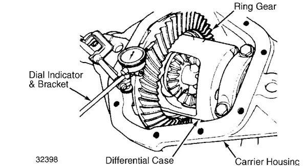
Fig. 15: Measuring Backlash Between Ring & Pinion Gears
2) Backlash reading between ring and pinion gears should be .004-.009" (.10-.23 mm). Maximum variation between readings at 3 points is .002" (.05 mm). If backlash is too high, move ring gear
closer to pinion gear. If backlash is too low, move ring gear away from pinion gear.
To change backlash readings, move shims from one side of
differential case to other. When backlash adjustment is completed,
check tooth contact pattern. See GEAR TOOTH CONTACT PATTERNS in this
section. Pattern should be correct if assembly and adjustments have
been done properly.
When differential is complete and correctly adjusted,
install new cover gasket and cover. Tighten cover bolts to 30-40 ft.
lbs. (41-54 N.m). Fill assembly with hypoid lubricant.
AXLE ASSEMBLY SPECIFICATIONS TABLE
Application Specifications In. (mm)
Pinion Gear Depth (Nominal Dimension)
Model 44 2.625 (66.68)
Model 60 & 61 3.125 (79.38)
Model 70 & 80 3.500 (88.90)
Ring Gear Backlash 004-.009 (.10-.23)
Side Bearing Preload 015 (.38)
INCH lbs. (N.m) Pinion Bearing Preload
New Bearings 20-40 (2.3-4.5)
Used Bearings 10-20 (1.1-2.3)
TORQUE SPECIFICATIONS
TORQUE SPECIFICATIONS TABLE
Applications Ft. Lbs. (N.m)
Axle Flange-to-Hub Bolt
Model 44 35 (48)
Models 60 & 61 55 (75)
Model 70 & 80 85 (115)
Pinion Shaft Flange Nut
Models 44 & 70 210 (285)
Models 60 & 61 270 (367)
Model 80 440-500 (597-678)
Ring Gear-to-Case Bolt
Model 44 55 (75)
Models 60, 61, & 70 110 (149)
Model 80 145-165 (196-223)
Side Bearing Cap Bolt 80 (108)
Front Axle
Cherokee, Comanche, & Wagoneer
Axle Shaft Nut 175 (237)
Disconnect Housing Bolt 10 (14)
Hub-to-Knuckle Bolt 75 (102)
Lower Control Arm Bolt 133 (180)
Lower Shock Mount Bolt 14 (19)
Drive Shaft Bolt 14 (19)
Stabilizer Bar Link Bolt 70 (95)
Tie Rod Nut 25-45 (34-61)
Upper Control Arm Bolt 37 (50)
Wheel Lug Nut 75 (102)
Grand Wagoneer
Leaf Spring "U" Bolt Nut 100 (136)
Lower Shock Mount Bolt 45 (61)
Drive Shaft Bolt 16 (22)
Spindle Attaching Nut 65 (88)
Tie Rod Nut 60 (80)
Wheel Lug Nut 80 (108)
