FUEL PUMP - ELECTRIC
1988 Jeep Cherokee
1988 Electric Fuel Pump JEEP
2.5L TBI, 4.0L MPFI
DESCRIPTION & OPERATION
Fuel system on 2 . 5L TBI models operate under constant fuel pressure of 14.5 psi (1.02 kg/cm). Fuel pressure regulator is mounted on throttle body assembly. Excess fuel pressure is returned to fuel tank. ECU has no control over fuel pressure relief valve. Fuel pump is immersible type with permanent magnet electric motor.
A frame mounted in-line fuel filter is used. Fuel pump is attached to fuel gauge sending unit in fuel tank. Voltage to operate pump is controlled by Electronic Control Unit (ECU). A ballast resistor is used in the fuel pump control circuit.
Ballast resistor is by-passed during start mode. During running mode, ballast resistor reduces speed of pump by lowering pump voltage. This ensures normal speed in running mode. The 1-ohm ballast resistor is mounted on right side of plenum chamber.
Fuel pump control relay is located on front of right strut tower. Battery voltage is supplied to relay from ignition switch. Relay is energized when ECU provides a circuit to ground.
A multi-cell, roller type pump is used on all 4.0L MPFI models. Pump and fuel filter are located on a plate, forward of rear axle. Fuel pump control relay location for 4.0L models is on right inner front fenderwell. Battery voltage is supplied to relay from ignition switch. Relay is energized when ECU provides a circuit to ground.
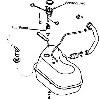
Fig. 1: 2.5L Fuel Pump & Fuel Gauge Sending Unit Courtesy of Chrysler Motors.
Pump contains 2 check valves. One valve relieves internal pump pressure and regulates maximum pump output. Second valve, located near pump outlet, restricts fuel movement in either direction when pump is not in operation. System operates under a constant fuel pressure of 31 psi (2.17 kg/cm).
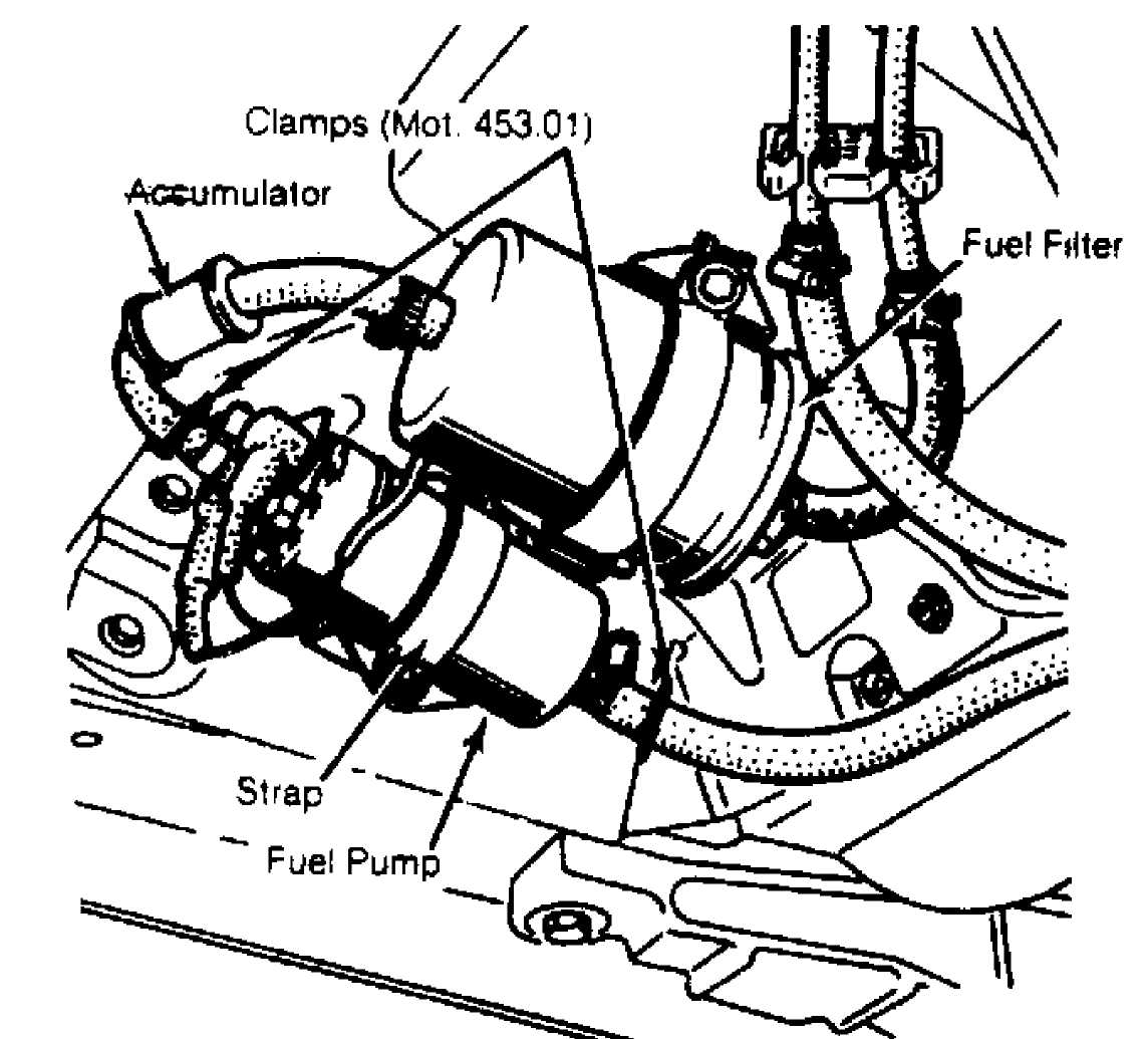
Fig. 2: 4.0L Fuel Pump, Filter & Accumulator Courtesy of Chrysler Motors
TESTING & DIAGNOSIS
FUEL PUMP PRESSURE TEST
2.5L TBI
1) Adjustment
of fuel pressure is required after replacement
of
pressure regulator. Remove air inlet from throttle body.
Connect
tachometer to diagnostic connector terminals D1-1 and
D1-3. Connect
fuel pressure gauge to fuel body pressure test
fitting.
NOTE: Some TBI models do not have a pressure test fitting on throttle body. Use Fitting (PN 8983 501 572) for this purpose.
2) Start
engine and accelerate to 2000 RPM. Turn
adjustment
screw to obtain 14.5
psi (1.02 kg/cm)
fuel pressure. Location of
adjustment
screw is on bottom of regulator. Install lead seal ball to
cover
regulator adjustment screw after adjusting fuel pressure
to
specification. Turn ignition off. Disconnect fuel pressure
gauge.
Install cap on test fitting.
Install air inlet.
NOTE: To increase fuel pressure, turn adjustment screw inward. To decrease fuel pressure, turn adjustment screw outward.
4.0L MPFI
Remove
cap from pressure test port in fuel rail. Connect
Fuel
Pressure Gauge (J-37730-1) to pressure fitting. Start
vehicle.
Pressure should be
approximately 31 psi (2.7 kg/cm)
with vacuum
hose connected to pressure
regulator.
Pressure
should be 39 psi (2.74 kg/cm)
with vacuum
hose removed from
regulator. If fuel pressure is not to
specifications,
check for kinks or restricting bends in fuel supply
and
return lines. Check fuel pump flow rate. Pump should deliver
minimum
of 1.06 quarts (one liter) of fuel per
minute with fuel
return line pinched
off.
If flow is
inadequate, check system for plugged fuel
filter or filter sock.
Fuel pump flow rate can be checked by
connecting a hose to fuel
test port on fuel rail and inserting other
end in clean
container.
To operate fuel pump, install a jumper wire into
diagnostic connector terminals D1-5 and D1-6. Pinch off fuel return line to ensure that no fuel returns to fuel tank. If fuel pressure is still not to specifications and fuel flow is normal, replace regulator.
REMOVAL & INSTALLATION
FUEL PUMP
Removal (2.5L TBI)
Disconnect
battery cables. Ensure fuel level is less than
1/2 for
this procedure. Remove fuel outlet and return hoses. Remove
sending
unit wires. Remove sending unit retaining lock ring.
Remove
sending unit/pump assembly with "O" ring
seal.
Disconnect fuel hose from fuel
pump. Disconnect wires from fuel pump.
Remove fuel pump from
sending unit.
Installation
Clean seal contact are of fuel tank. Install new "O" ring seal. Install a new filter on end of suction tube. Position sending unit/pump assembly in tank. To complete installation, reverse removal procedure. Start engine and check for leaks.
CAUTION: Fuel leaks can develop from over tightening sending unit/pump during installation.
Removal (4.0L MPFI)
Install clamps (MOT. 453.01) on fuel pump inlet and outlet hoses. Disconnect hoses from fuel pump. Disconnect electrical connectors. Remove retaining strap. Remove fuel pump.
Installation
To install, reverse removal procedure. Ensure that clamps (MOT. 453.01) have been removed from fuel lines. Start engine and check for leaks.
NOTE: Accumulator is located between fuel pump and fuel filter on 4.0L models.